
In the engineering of high-capacity transmission systems—ranging from multi-megawatt wind turbine main shafts to heavy-duty marine propulsion—the mechanical integrity of a forged stepped shaft is determined long before the final machining stage. While the forging process provides the initial grain flow refinement, the ultimate fatigue life and load-carrying capacity are dictated by the synergy between Material Selection and the Quenching & Tempering (Q+T) protocol.
For R&D and Procurement Directors in the heavy industrial sector, the primary challenge is the “Mass Effect.” Large-diameter stepped shafts, characterized by significant variations in cross-sectional geometry, present a metallurgical paradox: how to achieve a uniform Hardness Gradient and a fully transformed Tempered Martensite microstructure in the core without inducing quench cracks or excessive residual stresses at the transition shoulders.geometric complexity of stepped shaft manufacturing
At Yansen Forging, we approach the production of heavy-duty shafts not merely as a shaping exercise, but as a precise metallurgical intervention. This article explores the critical parameters of heat treatment and material science required to ensure that a forged shaft meets the rigorous demands of ASTM and EN standards.
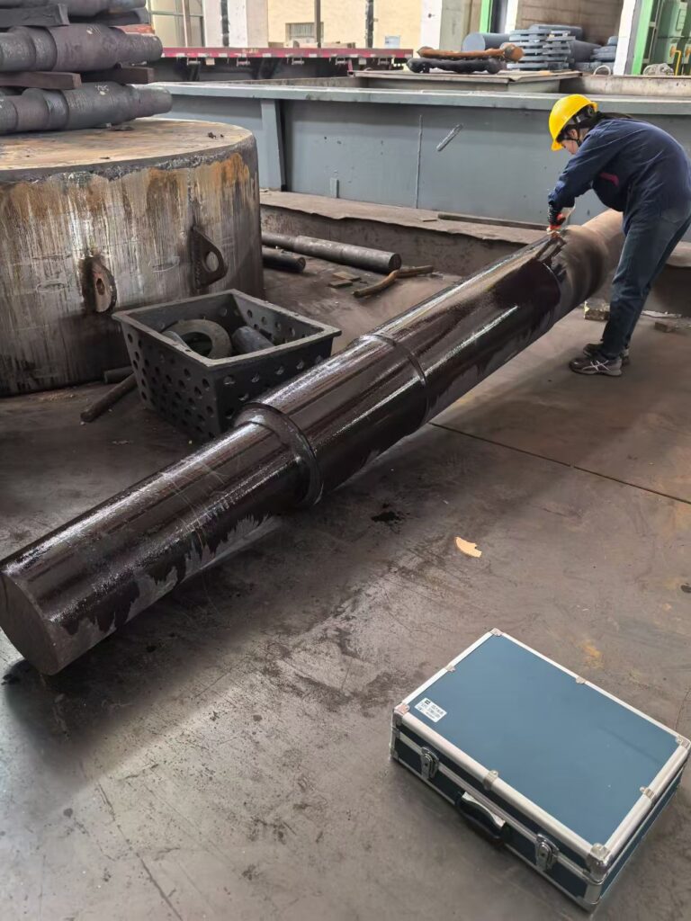
1. The Material Showdown: 42CrMo4 vs. 34CrNiMo6
The selection of alloy steel is the first critical decision point. The “hardenability” (the ability of a steel to transform to martensite at a given depth) is the limiting factor in heavy-section shafts.
42CrMo4 / AISI 4140: The Mid-Range Workhorse
42CrMo4 (1.7225) is a chromium-molybdenum alloy widely utilized for its excellent strength-to-weight ratio and fatigue resistance. However, its Hardenability—often measured via the Jominy end-quench test—is finite.
- Limitation: In sections exceeding 150mm–200mm, the cooling rate at the core often falls below the critical cooling rate required for full martensitic transformation.
- Result: The core may consist of a mixture of upper bainite and pearlite, which significantly reduces the yield strength and impact toughness compared to the surface. For shafts with a diameter
>250mm>250mm, 42CrMo4 often fails to provide the necessary core mechanical properties required for high-torque applications.
34CrNiMo6 / AISI 4340: The Deep-Hardening Solution
For heavy-duty transmission shafts (e.g., wind turbine main shafts or large gearbox input shafts), 34CrNiMo6 (1.6582) is the preferred specification. The addition of 1.30% to 1.70% Nickel (Ni) serves a dual purpose:
- Increased Hardenability: Ni shifts the Continuous Cooling Transformation (CCT) diagram to the right, allowing for a fully martensitic structure even at slower cooling rates in the core of large sections (up to 400mm-500mm).
- Low-Temperature Toughness: Ni significantly improves the Charpy V-Notch (CVN) impact energy, which is critical for equipment operating in offshore or arctic environments where sub-zero temperatures can induce brittle fracture.
2. Technical Deep-Dive: The Quenching & Tempering (Q+T) Process
The Q+T process is the most high-risk phase of stepped shaft manufacturing. At Yansen Forging, we utilize a data-driven approach to mitigate the risks associated with geometric complexity.
Austenitizing and Soaking Time
The shaft is heated to the austenitizing temperature, typically 850∘C±10 for 42CrMo4. The “Soaking Time” is calculated based on the maximum diameter section (Dmax). A common metallurgical rule of thumb is 1 hour of soaking per 25mm of thickness once the core reaches temperature. Precise control prevents Grain Coarsening, which would otherwise degrade the fracture toughness of the final product.
Quenching Medium and the “Stepped” Challenge
The transition zones (shoulders) of a stepped shaft are high-stress areas. During quenching, the thinner sections cool faster than the thicker sections, creating a Thermal Gradient and Transformational Stress.
- Polymer Quenching: We often utilize high-concentration polymer quenchants. Unlike water (which is too aggressive and risks quench cracking) or oil (which may be too slow for deep hardening), polymers allow for a tunable cooling rate.
- Agitation Systems: High-volume agitation is mandatory to break the Leidenfrost effect (the vapor blanket stage), ensuring uniform heat extraction across the entire surface of the shaft to prevent soft spots.
Tempering for Stress Relief and Ductility
Immediately following quenching (while the shaft is still “hand-warm” at approximately 60−80∘C), it must be charged into the tempering furnace. Tempering at 550∘C to 680∘C transforms the brittle “as-quenched” martensite into Tempered Martensite, providing the required balance of Tensile Strength (Rm) and Elongation (A).
3. Hardness Gradient: The Ultimate Metric of Integrity
For a procurement director, the surface hardness (e.g., 280-320 HBW) is only half the story. The Hardness Gradient—the variation in hardness from the surface to the center—is the true indicator of a shaft’s performance under cyclic loading.
Core Hardness Verification
In heavy-duty gearboxes, the shaft core must withstand significant torsional shear stresses. If the hardness gradient is too steep (i.e., the core is significantly softer than the surface), the shaft may suffer from premature fatigue failure or permanent deformation. At Yansen Forging, we verify the gradient through:
- Prolongation Testing: We forge an extra length (prolongation) on the shaft, which is heat-treated as an integral part of the workpiece. This prolongation is then cut and tested at the
1/21/2radius and center positions to confirm core properties. - Stress Relieving: After rough machining, a Stress Relieving cycle (typically
30−50∘C30−50∘Cbelow the tempering temperature) is performed. This ensures dimensional stability during final precision grinding, preventing the “warping” that often plagues lower-quality shafts.
4. Crucial NDT Inspection After Q+T
Heat treatment can occasionally reveal or induce internal defects. A rigorous Non-Destructive Testing (NDT) regime is non-negotiable for high-end European and American OEMs.
Ultrasonic Testing (UT) per EN 10228-3
We perform 100% UT scanning after Q+T. We specifically look for:
- Hydrogen Flakes: Also known as “shatter cracks,” these are internal ruptures caused by hydrogen embrittlement during cooling.
- Thermal Cracks: Internal ruptures caused by the volumetric expansion during the martensitic transformation.
- Requirement: Most heavy-duty applications require compliance with EN 10228-3 Class 3 or Class 4, ensuring no detectable internal discontinuities.
Magnetic Particle Testing (MT) per EN 10228-1
The radii of the stepped shaft are the primary sites for stress concentration. MT is employed to detect any surface-breaking micro-cracks that may have formed during the rapid cooling phase of the quench.
5. Summary Technical Table: AISI 4140 vs. AISI 4340 Forged Shafts
The following table provides a comparative analysis for procurement decision-making regarding large-diameter forged shafts.
| Parameter | 42CrMo4 / AISI 4140 | 34CrNiMo6 / AISI 4340 |
| Hardenability Limit (Dia.) | Up to 150mm (Full Martensite) | Up to 450mm (Full Martensite) |
| Typical Surface Hardness | 260 – 320 HBW | 280 – 340 HBW |
| Core Hardness (at 200mm) | Significant Drop-off (< 240 HBW) | Uniform (within 10% of surface) |
| Low-Temp Toughness | Moderate (−20∘C−20∘C) | Superior (−40∘C−40∘C or lower) |
| Alloying Strategy | Cr-Mo (Cost-Effective) | Cr-Ni-Mo (High Performance) |
| Typical Applications | Conveyor shafts, small gear shafts | Wind turbine mains, marine propulsion |
6. Conclusion: The Yansen Forging Advantage
In the world of heavy-duty transmission, a “forged shaft” is not a commodity; it is a precision-engineered component. The difference between a shaft that lasts 20 years and one that fails in 24 months lies in the metallurgical rigor of the heat treatment process and the accuracy of the hardness gradient control.
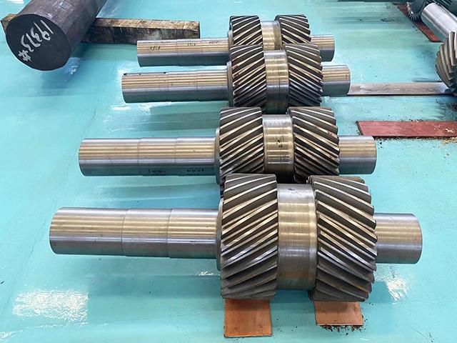
By specifying the correct alloy—whether it be the versatile 42CrMo4 or the deep-hardening 34CrNiMo6—and enforcing strict Q+T protocols, Yansen Forging ensures that every stepped shaft delivered to our global partners meets the highest standards of E-E-A-T (Experience, Expertise, Authoritativeness, and Trustworthiness).complementary forged gear blanks for heavy-duty transmissions
Contact our engineering team today to discuss your specific requirements for hardness profiles, NDT standards, and material specifications for your next heavy-duty project.
Metallurgy of Forged Stepped Shafts: Optimizing Heat Treatment and Hardness Gradient for Heavy-Duty Performance
In the engineering of high-capacity transmission systems—ranging from multi-megawatt wind turbine main shafts to heavy-duty…
Manufacturing Engineering of Forged Stepped Shafts: Optimizing Grain Flow for Heavy-Duty Transmission
In the design of high-torque transmission systems—ranging from industrial gear reducers(For complete gearbox assemblies, we…
Advanced Gear Blank Manufacturing: Why Seamless Forging Outperforms Casting for Heavy-Duty Power Transmission
In the demanding sectors of offshore wind energy, deep-pit mining, and maritime propulsion, the gear…
Seamless Rolled Ring Forging vs. Casting & Welding: The Ultimate Guide for Heavy Industry
In the demanding sectors of wind energy, aerospace, and heavy industrial manufacturing, the structural integrity…
Open Die Forging vs. Closed Die Forging for Large-Scale Forged Shafts: A Technical Comparison for Engineers
In the realm of heavy machinery, the structural integrity of a power-transmitting component is non-negotiable….
Forged Gear Rings: The Seamless Solution for High-Performance Gear Blanks
For procurement managers and engineers in the heavy machinery sector, the reliability of a gear…